

|
|
|
|---|---|---|
Do you need to deply sensor nodes in a wide area with big distances between the nodes and have all nodes to be able to send sensor data to the cloud? LoRa would be the right choice as it is a long range low power communication technology. LoRa is a long range low power communication technology. Using LoRa there are at least 3 possible scenarios:
For the mentioned scenario where a large area needs to be covered, options (1) and (2) have some
disadvanteges.
Option (1) will require to make sure enough gateways are available to have all sensor nodes in the
range of a gateway. This can be quite expensive and all of these gateway will need a separate connection to the
cloud.
Option (2) might not be able to have connectivity of all nodes to each other which might not be feasable. And
forwarding the sensor data to the cloud might not be easy to realize as well.
Based on this, a LoRa mesh network
might be the best solution. Connectivity to the cloud can be implemented in one of the nodes, read on to see a
proposal how to do it.
Requires the Queue library from SMFSW ==> https://github.com/SMFSW/Queue
In this PoC, a LoRa mesh network is realized on top of the RAKwireless RUI3 API. Using the RUI3 API keeps all the
communication functionality outside of the application code and setup of the device can be done through API calls or
with the integrated AT commands.
This PoC will shows how to setup the mesh and have a dedicated node which has
the connectivity to send the sensor data to the cloud.
One configuration option is that each mesh node can send packets to and receive packets from any other node:
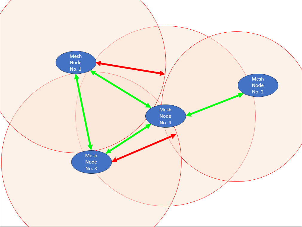
| Node 1 | Node 2 | Node 3 | Node 4 |
|---|---|---|---|
| node 1 - itself | node 2 itself | node 3 itself | node 4 itself |
| node 3 - direct | node 4 direct | node 1 direct | node 1 direct |
| node 4 - direct | node 1 forward over node 4, 1 hop | node 4 direct | node 2 direct |
| node 2 - forward over node 4, 1 hop | node 3 forward over node 4, 1 hop | node 2 forward over node 4, 1 hop | node 3 direct |
In this configuration, nodes 1,3 and 4 can directly communicate to each other, while node 2 is out of range of node 1
and 3.
But due to the mesh map node 1 knows the existence of node 2, even it cannot see the packets coming from
it. When it sends a packet to the address of node 2, the packet will be forwarded by node 4 which is in range of
node 2.
But in this configuration it would be difficult to send the sensor data to the cloud, as it is not clear, which of the nodes has to connection to the cloud.
Another mesh configuration can declare one node as a master node and all other nodes are addressing their data packets to this master node:
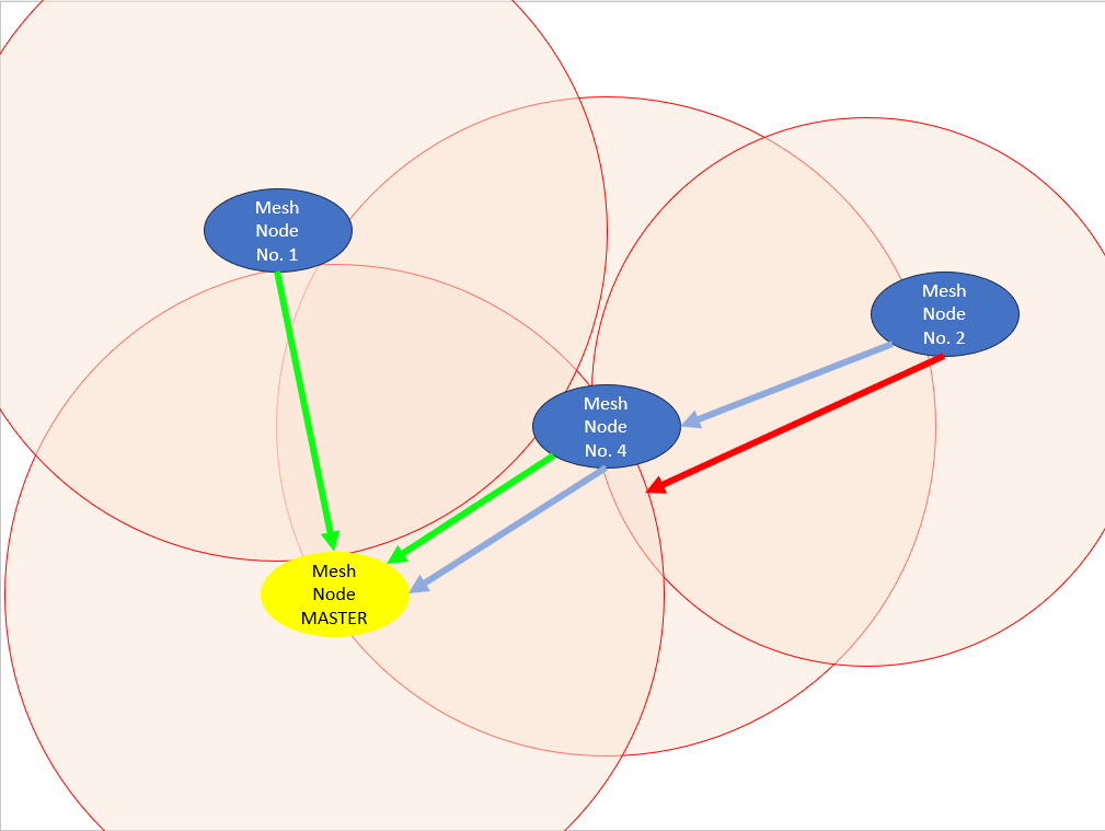
The mesh map of each node would still look the same as above. But the communication of nodes 1, 2 and 4 would be all addressed to the master node (former node 3). In this configuration, nodes 1,3 and 4 can directly communicate to the master node, while node 2 would use node 4 to forward its data packets to the master node.
This configuration is fitting best for the application scenario. The dedicated master node will be the one which has the connectivity to the cloud.
This example code can cover both scenarios. The master node address can be defined on each of the nodes with an AT command (or can be hard-coded in the application code, which is not recommended).
To be able to build the mesh map, each node needs a unique ID or node address.
Again there are at least two
options to assign a node address:
In the example code, the option (2) is used and the node adresses are created from the LoRaWAN DevEUI that is stored
in flash of every RAK WisDuo module during production. Each nodes address is 4 bytes long. This means that each node
can be flashed with exactly the same firmware.
Using the option (1) can reduce the space that the address
occupies in a data packet by limiting the address to a value between 1 and 255. But this means mean that each node
has to be flashed with a specific firmware or that each node has to be assigned a node address manually through an
AT command.
The node address is obtained and assigned automatically during the setup process. The application does not need to handle it.
After power up or reboot, each nodes start to send out its own mesh map, which at that time will only include its own
node address. This map is in a different format than the data packets and is sent as a broadcast.
Each node that
receives the mesh map will compare it with its own mesh map and extend it with missing nodes from the received map.
Then it sends out its updated new mesh map.
After a short time all nodes in the map will have an updated mesh map
with all nodes in it and the information if a specific node is in direct range or needs to be contacted through one
or multiple other nodes.
In the beginning the nodes send out the mesh map every 30 seconds, but after a while, the interval is reduced to save power.
In addition, if a node receives a data packet with a node address that is not listed in its own mesh map, it will re-initiate a mesh initialization by sending out its own mesh map. This helps to accelerate an update of the mesh map in each node if a node joins after all other nodes have already finished their map initialization.
The initialization of the mesh map in each node is handled in the background. The application does not need to handle it by itself.
General requirements
Both requirements can be set with AT commands through the USB connection of the WisBlock Base Boards.
If the P2P parameters are fixed for all scenarios where the devices will be used, they can be setup as well in the
setup call like this:
    // Set LoRa P2P configuration
    api.lora.nwm.set();

    /// \todo this should be done by AT commands!
    // AT+P2P=916000000:7:0:1:8:5
    api.lora.pfreq.set(916000000);
    api.lora.psf.set(7);
    api.lora.pbw.set(0);
    api.lora.pcr.set(1);
    api.lora.ppl.set(8);
    api.lora.ptp.set(5);
Additional functions in the application
The mesh network requires two callback functions in the
application code:
on_mesh_data_. It will decode
the received data (a counter and 2 sensor data values) and print the values through the USB connection.
map_changed_cb_. It will wake the
application handler and print out the changed map through the USB connection.void on_mesh_data(uint32_t fromID, uint8_t *rxPayload, uint16_t rxSize, int16_t rxRssi, int8_t rxSnr)
{
Serial.println("-------------------------------------");
Serial.printf("Got data from node %08lX\n", fromID);
longlong_byte_u new_counter;
// Demo output of the received data packet
memcpy(new_counter.b_values, &rxPayload[0], 8);
Serial.printf("Counter %Ld\n", new_counter.l_value);
memcpy(new_counter.b_values, &rxPayload[8], 8);
Serial.printf("Sensor Value 1 %Ld\n", new_counter.l_value);
memcpy(new_counter.b_values, &rxPayload[16], 8);
Serial.printf("Device %08lX\n", new_counter.l_value);
Serial.println("-------------------------------------");
}
void map_changed_cb(void)
{
// No actions required, but can be used to react to a change in the Mesh Map
// Do not use long code here, just set a flag and handle the event in the app_event_handler()
g_task_event_type |= MESH_MAP_CHANGED;
}
_g_task_event_type_ is used in the timed_loop to
determine which events have to be handled.
Beside of the two callbacks, the mesh handler has to be called in the LoRa P2P TX and RX callbacks
_recv_cb and send_cb
In _recv_cb_ the received packet is put in a queue for processing. The received data is
not processed in the callback to be able to receive packets without delay.
void recv_cb(rui_lora_p2p_recv_t data)
{
    // Save RX packet in queue to be processed by the mesh handler
    if (!add_rx_packet(data.Rssi, data.Snr, data.BufferSize, data.Buffer))
    {
        MYLOG("RX-P2P-CB", "RX queue is full");
    }
}
In _send_cb the mesh function mesh_check_tx_ is
called to check if there are more packets to be sent.
void send_cb(void)
{
    MYLOG("TX-P2P-CB", "P2P TX finished");
    digitalWrite(LED_BLUE, LOW);
    // Check what to do after successful TX
    mesh_check_tx();
}
Above code is a simplified version.
The initialization of the LoRa transceiver will be handled in the background by the RUI3 API.
The initialization of the mesh map will be automatically started as well and handled by a timer triggered every 1
second that is started in setup. This timer calls
_timed_loop_ that is checking the event flag
g_task_event_type_ for required actions and is as well calling the mesh event handler.
To initialize the mesh network the pointers to the above mentioned callbacks have to submitted to the mesh init
function.
Beside of the mesh event callbacks the LoRa event callbacks are initialized here as well.
    g_mesh_events.data_avail_cb = on_mesh_data;
    g_mesh_events.map_changed_cb = map_changed_cb;

    // Initialize the LoRa Mesh
    // * events
    init_mesh(&g_mesh_events);
    // Setup callbacks
    g_mesh_events.data_avail_cb = on_mesh_data;
    g_mesh_events.map_changed_cb = map_changed_cb;
    api.lora.registerPRecvCallback(recv_cb);
    api.lora.registerPSendCallback(send_cb);
    api.lora.registerPSendCADCallback(cad_cb);

    // Initialize the LoRa Mesh * events
    init_mesh(&g_mesh_events);
Important step here is to set the LoRa transceiver to permanent RX mode. Here the method of permanent RX with TX allowed is used.
    // Enable RX mode (always with TX allowed)
    api.lora.precv(65533);
To send data each node has two options:
First a dummy sensor data packet is prepared. It consists of a counter and two additional data fields, one filled with the counter value, the other one filled with the node ID. In a final application, this would be replaced with real sensor values.
            // Create a dummy data packet with 2x 64bit counter value + device address
            msg_cnt++;

            convert_value.l_value = msg_cnt;
            memcpy(&data_buffer[0], convert_value.b_values, 8);
            memcpy(&data_buffer[8], convert_value.b_values, 8);
            convert_value.l_value = g_this_device_addr;
            memcpy(&data_buffer[16], convert_value.b_values, 8);
Next the destination address is prepared. To which node the packet is sent depends whether a master node was defined with _AT+MASTER=hhhhhhhh__ or not.
            // Select a random node from the map
            uint8_t selected_node_idx = 0;
            // Select broadcast as default
            bool use_broadcast = true;
            // Target node address;
            uint32_t node_addr = 0x00;

            if (g_custom_parameters.master_address != 0)
            {
                node_addr = g_custom_parameters.master_address;
                g_nodes_list_s route;
                // Check if we have a route to the master
                if (get_route(g_custom_parameters.master_address, &route))
                {
                    MYLOG("APP", "Send to master node %08lX", g_custom_parameters.master_address);
                    use_broadcast = false;
                }
                else
                {
                    // No route, send as broadcast
                    MYLOG("APP", "No route to master node %08lX", g_custom_parameters.master_address);
                    use_broadcast = true;
                }
            }
            else
            {
                // Get the number of nodes in the map
                uint8_t node_index = nodes_in_map() + 1;
                // MYLOG("APP", "%d nodes in the map", node_index);

                // Check how many nodes are in the map
                if (node_index > 2)
                {
                    // Multiple nodes, select a random one
                    selected_node_idx = (uint8_t)random(1, (long)node_index - 1);
                    use_broadcast = false;
                    MYLOG("APP", "Using node %d", selected_node_idx);
                }
                else if (node_index == 2)
                {
                    // Only 2 nodes in the map, send to the other one
                    selected_node_idx = 1;
                    use_broadcast = false;
                    MYLOG("APP", "Using node 1");
                }
                else
                {
                    // No other node, lets send a broadcast
                    selected_node_idx = 0;
                    use_broadcast = false;
                    MYLOG("APP", "Using broadcast");
                }
                node_addr = get_node_addr(selected_node_idx);
                // MYLOG("APP", "Got receiver address %08lX", node_addr);
            }
To send the data through the mesh, a simple call to _send_to_mesh_ is used. The
function requires as parameters
        // Enqueue the data package for sending
        uint8_t data_size = 24;
        if (!send_to_mesh(use_broadcast, node_addr, (uint8_t *)data_buffer, data_size))
        {
            MYLOG("APP", "Could not enqueue packet for sending");
        }
This is a non-blocking call. The data is saved in a message queue. The message queue is handled in the background by
the _timed_loop and each message is sent one by one.
By default the message queue can have
four entries. This is sufficient for the example code, but if you have to send a lot of data, you might need to
increase it more entries in the file mesh.cpp_.
Keep in mind that each entry requires a
certain amount of memory and with a large queue you might get to the limit. On a RAK3172 this can lead to an error
due to insufficient avaialbel memory.
/** Max number of messages in the queue */
#define TX_QUEUE_SIZE 4
Beside of the standard RUI3 API AT commands, the example code adds two more AT commands that are specific to the Mesh Network.
Description: Set or get the current master node address
This command allows to read or set the mesh address of the master node. The master node address can be disabled by
setting it to FFFFFFFF`
| Command | Input Parameter | Return Value | Return Code |
|---|---|---|---|
| ATC+MASTER? | - | `ATC+MASTER: "Set/get Master Node address" | OK |
| ATC+MASTER=? | - | <Master Node Address> | OK |
| ATC+MASTER=<Input Parameter> | <Master Node Address> | - | OK or +CME ERROR:6 |
Examples:
ATC+MASTER?
ATC+MASTER:"Set/get Master Node address"

ATC+MASTER=?
ATC+MASTER=CBE0E4F5
OK

ATC+MASTER=CBE0E4F5
OK

ATC+MASTER=CBE0E4
+CME ERROR:6
OK
Description: Get the mesh map
This command allows to read the mesh map. It is a read only function.
| Command | Input Parameter | Return Value | Return Code |
|---|---|---|---|
| ATC+MESH? | - | `ATC+MESH: "Get the mesh map" | OK |
| ATC+MESH=? | - | <Mesh (multiline)> | OK |
Examples:
ATC+MESH?
ATC+MESH:"Get the mesh map"


ATC+MESH=?
ATC+MESH=
#01: 6FA6BC6C ^^
#02: 2BD56908 <->
#03: CBE0E4F5 <->

OK
Explanation for the map^^ means this node, it is always the first address
in the map<-> means the node is in range of this
node->nnnnnnnn #h: m means the node is not in direct range. It is
bridged through the node with the address nnnnnnnn and is
m hops away.
The application supports as well the RAK1921 OLED display.
The display can be used for testing the mesh network
and to find location to place mesh nodes within reach of other nodes.
The display can show two different
information, depending on the #define SHOW_MAP being set or not.
| Status | Display content |
|---|---|
#define SHOW_MAP |
Display shows the Mesh Map |
// #define SHOW_MAP |
Display shows received packets, with nodes, RSSI and SNR |